- COMPETITIONS
- THE COMPETITION ARCHIVES
- RRBBO OFFICIAL COMPETITIONS
- BUILD OFF 15 (2020)
- BUILD OFF 15 - CLASS 1 - BUILD JOURNALS
You are using an out of date browser. It may not display this or other websites correctly.
You should upgrade or use an alternative browser.
You should upgrade or use an alternative browser.
BO15 WAHA-SEDB-3 (TRIKE-TOR...2nd Place)
- Thread starter MazdaFlyer
- Start date


Help Support Rat Rod Bikes Bicycle Forum:
This site may earn a commission from merchant affiliate
links, including eBay, Amazon, and others.


Late to the party on this one but its looking good! Your designs are very much "low trail." The current trend in curing speed wobble in low trail bikes is with a headset with friction washers built in to add resistance in the steering system. The added resistance might also help control your steering input. You may be able to just attach a torsion spring with one end to the frame and the other to the stem/fork?
Hey thanks for dropping by. I hadn’t hear the term “low trail” used before. My previous direct steer used a couple of tension compression springs. They calmed things down and I had the headset tight. I’ll probably experiment with your resistance ideas. I still have the springs and a couple of gas struts that might work as dampeners.
I don’t have AutoCad or Revit computer access anymore. So I’m in a sketch mentality at present. In off build time I gave some thought 2 dimensionally to the steering geometry. I may get out my old drafting board and tools and do a scale layout.

It really can’t be this difficult, just similar to basic go cart steering. I did notice I have some binding on a couple of bolts that need to be shorter with the present setup.
I’m also going to secure the frame to crossbeam with 4 bolts to simulate a Ubolt connection.
While I was working on this today, our neighbor asked if I work on bikes. She had inherited a tricycle, said it was pulling to right when she rode it, wants to haul her dog.
Food for thought

- Joined
- Aug 14, 2019
- Messages
- 816
- Reaction score
- 2,221
That made me think of a little wooden go kart that my father made for us kids with a rope winding steering wheel that was backwards by mistake. lol It was fun to try to ride it before he fixed it.
A friend and I did the same thing with a mini hydroplane we built.
What about a connection between the fork dropouts that becomes the central point of rotation, kinda like in KF’s pic above, (other aspects aside) so you’re not dealing with the change in Z axis from the fork? Making it like the steering tube ‘virtually’ extended all the way.
Adding thoughts... I’m sure you’ll get it. Gonna be awesome.
Adding thoughts... I’m sure you’ll get it. Gonna be awesome.
Good overview of Ackerman steering concept. If anyone else watching this build wants to try their hand at this madness the video, at least the first half or so is well worth watching. I wish I’d seen it earlier.
Captain Awesome you must be awesome...thanks!
What about a connection between the fork dropouts that becomes the central point of rotation, kinda like in KF’s pic above, (other aspects aside) so you’re not dealing with the change in Z axis from the fork? Making it like the steering tube ‘virtually’ extended all the way.
Adding thoughts... I’m sure you’ll get it. Gonna be awesome.
That was sorta my original thought, but I got sidetracked on the reversed steering issue. Thank you.
When it stops raining I’ll get back on this, after the last few posts and Video that CA posted I think I’m on track. Hoping to just adjust things. Going to find some string and play with a triangle. I think things are in the ball park, just a little tune up left. Optimism or false hope, we’ll see.
I'm no engineer, but to me the go kart steering that KF posted is what I've been thinking all along on this, just wasn't sure how the connection would happen. It takes the 'getting both of the steering arms exactly centered and both moving in unison' out of the equation. It's just one action and reaction of the single steering shaft (don't know actual terms) and the rod that ties the two wheels together. Seems more simple, and less chance of failure / extended maintenance.
- Joined
- Aug 14, 2019
- Messages
- 816
- Reaction score
- 2,221
I just thought of something. I'm guessing the angle of the fork is designed to work the best for that frame. Maybe that is the amount of caster you should put into your cross beam. That should align your spindles to be on the same plane, provided you have the correct length on the forks.
Thoughts anyone?
Thoughts anyone?
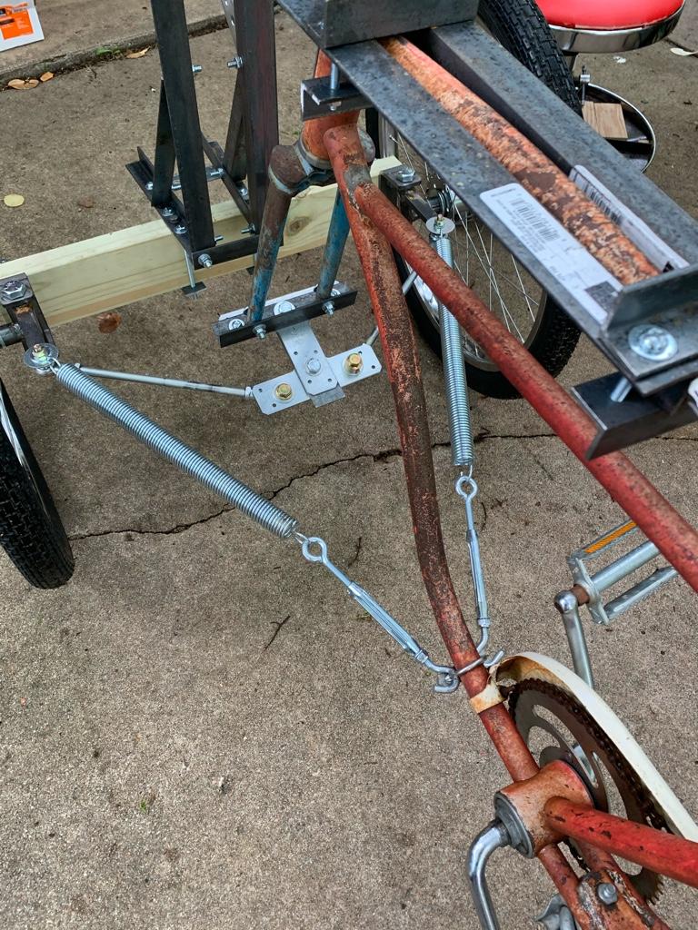
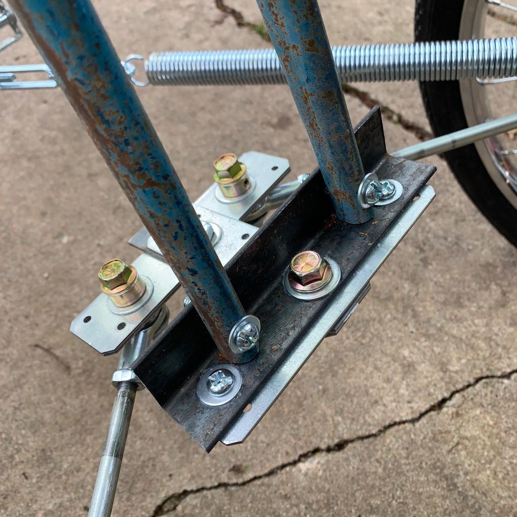
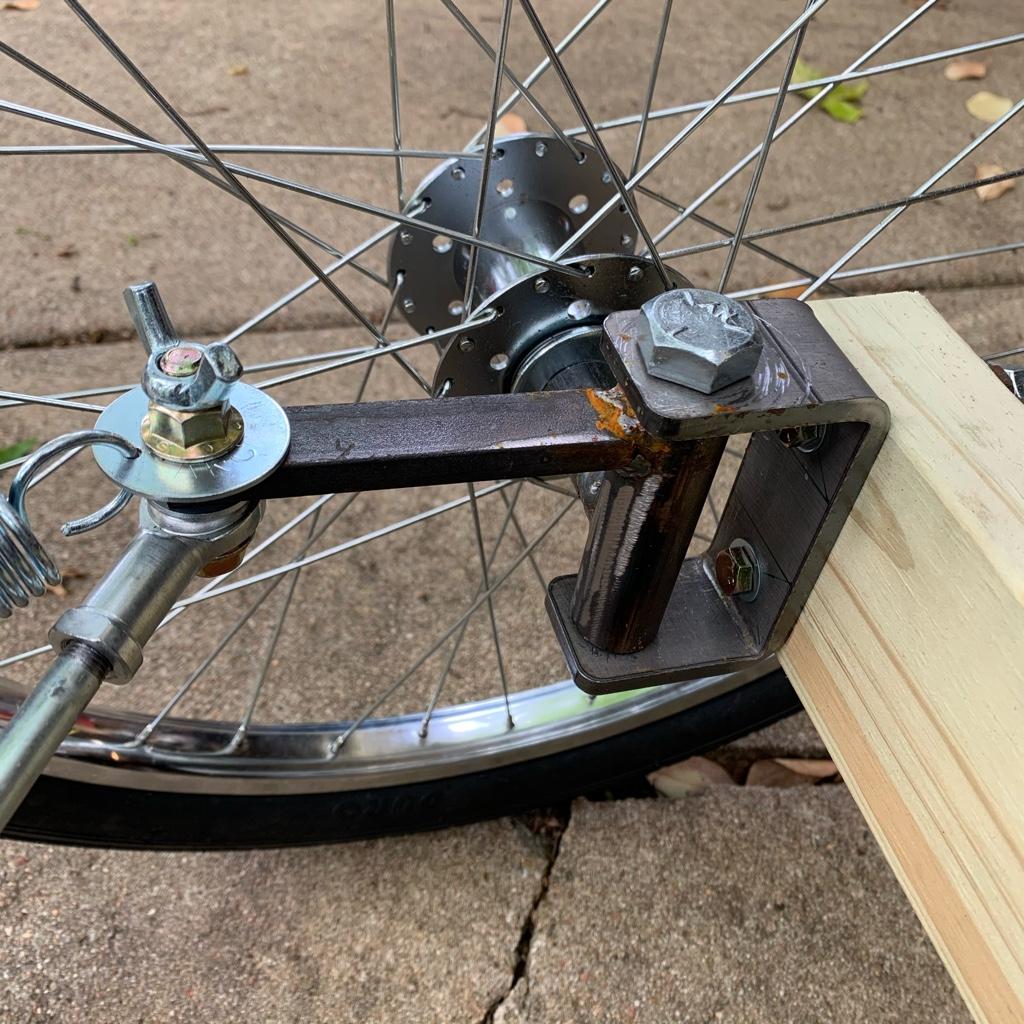
Between rain a little progress today. I roughed out a new bracket.
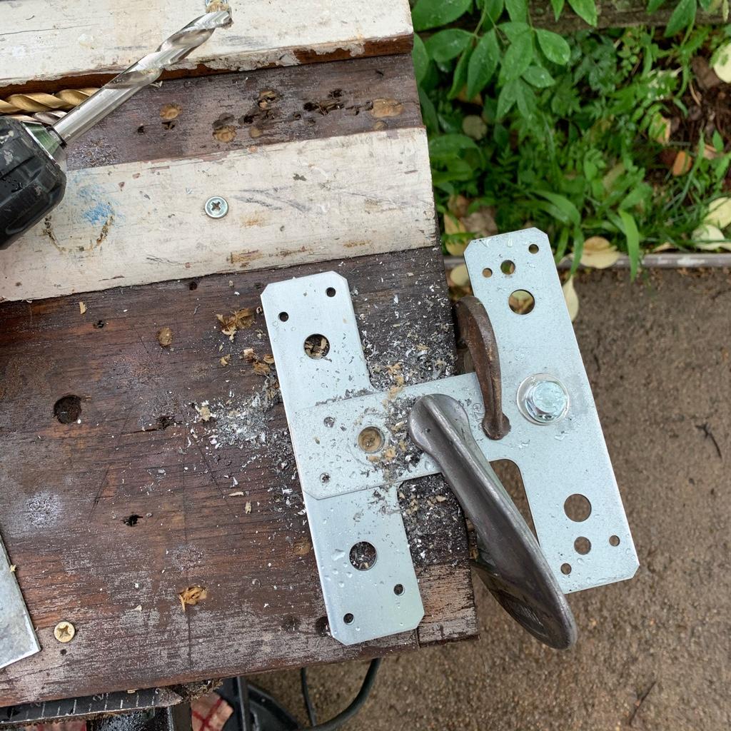
After mounting it up and doing a test I discovered that my angle frame work had decided to move. Added a temporary clamp to mark desired position. And cut new rods for the dual mount.
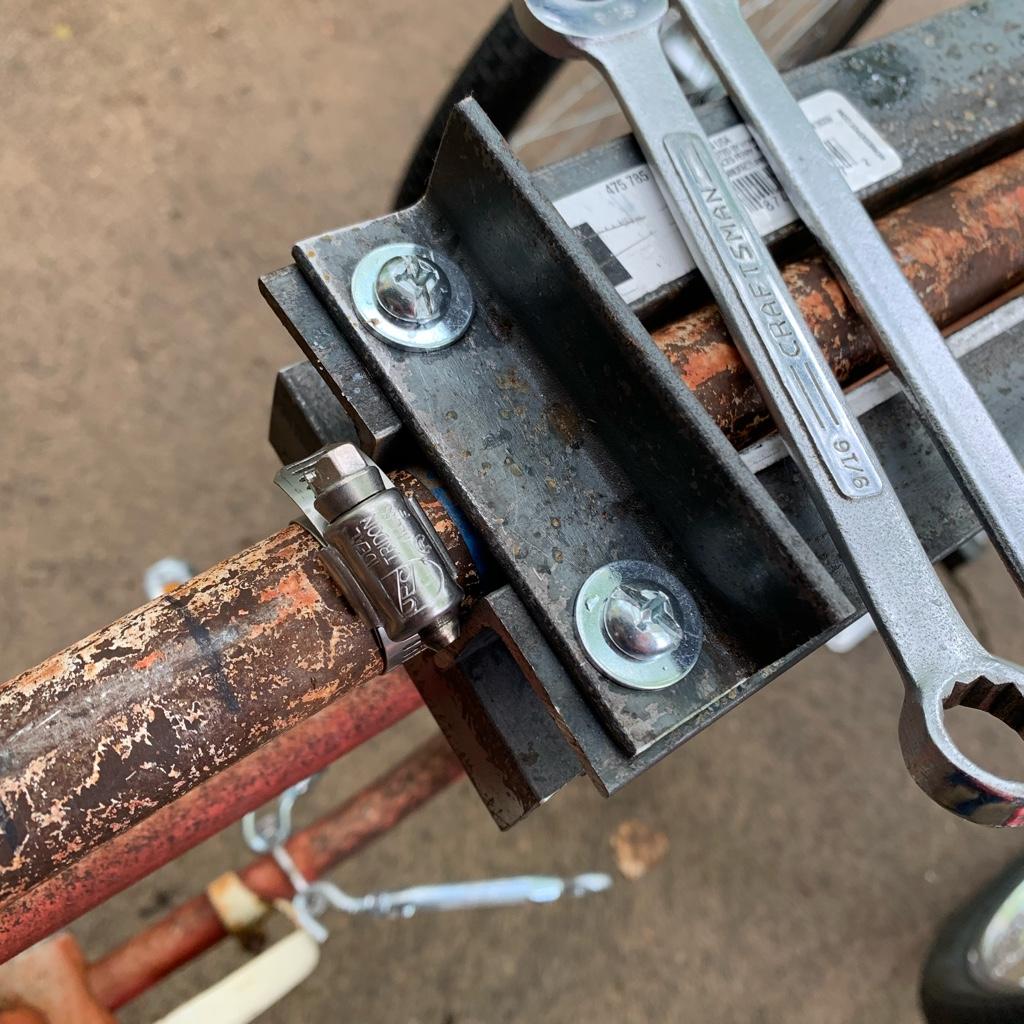


Also added my axle beam safety bolts and clamp.
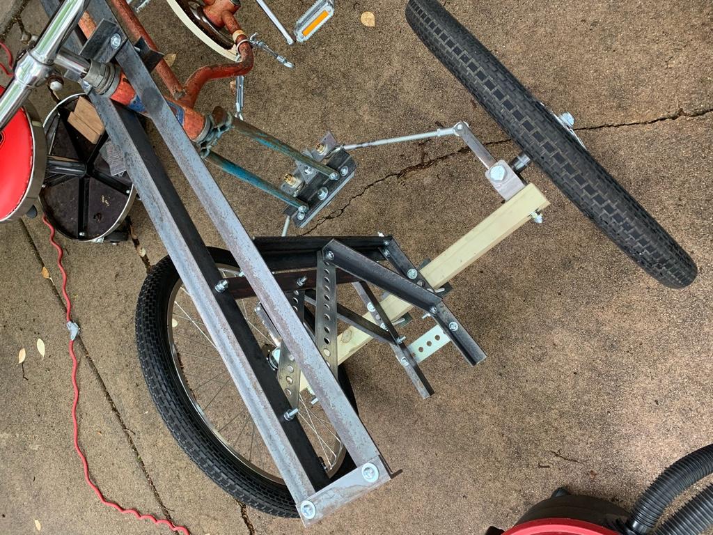
The current setup seems to work OK but I think the single “T” bracket pivot worked smoother. There is possible issue of steering not centering back up with the dual pivot “H” bracket. It also feels looser. The “T” bracket seemed tighter.
The current setup...need to experiment with the springs for return and dampening.
After mounting it up and doing a test I discovered that my angle frame work had decided to move. Added a temporary clamp to mark desired position. And cut new rods for the dual mount.
Also added my axle beam safety bolts and clamp.
The current setup seems to work OK but I think the single “T” bracket pivot worked smoother. There is possible issue of steering not centering back up with the dual pivot “H” bracket. It also feels looser. The “T” bracket seemed tighter.
The current setup...need to experiment with the springs for return and dampening.
Last edited:
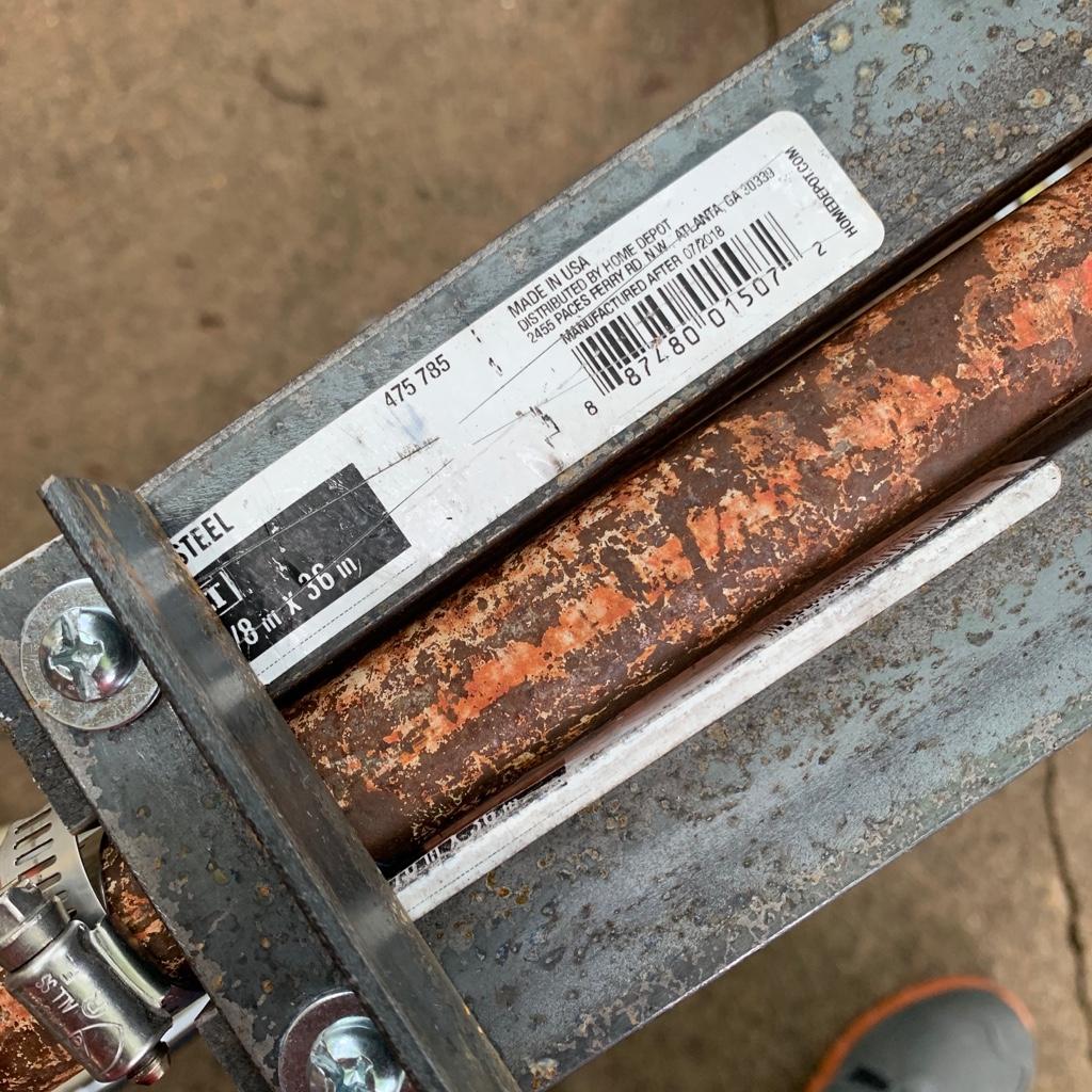
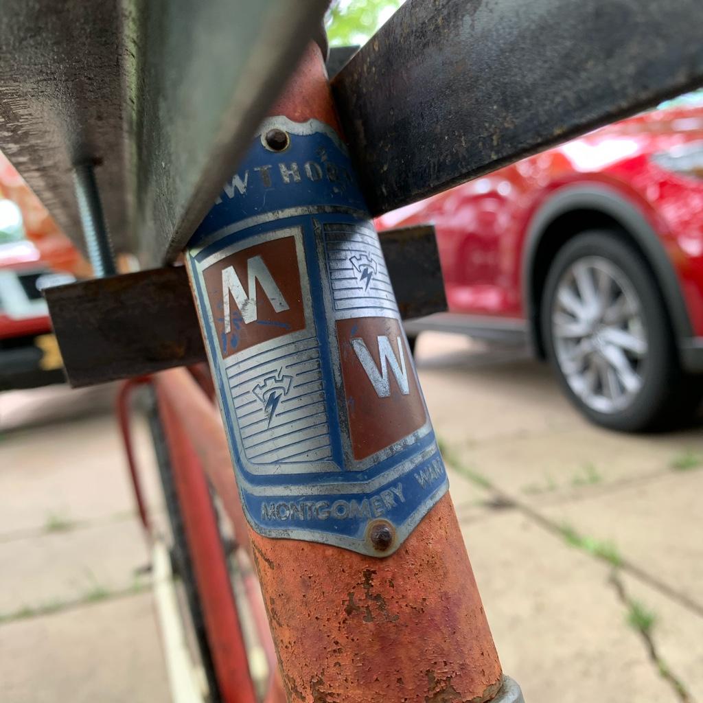
And I noticed the “Made In USA” label on steel.
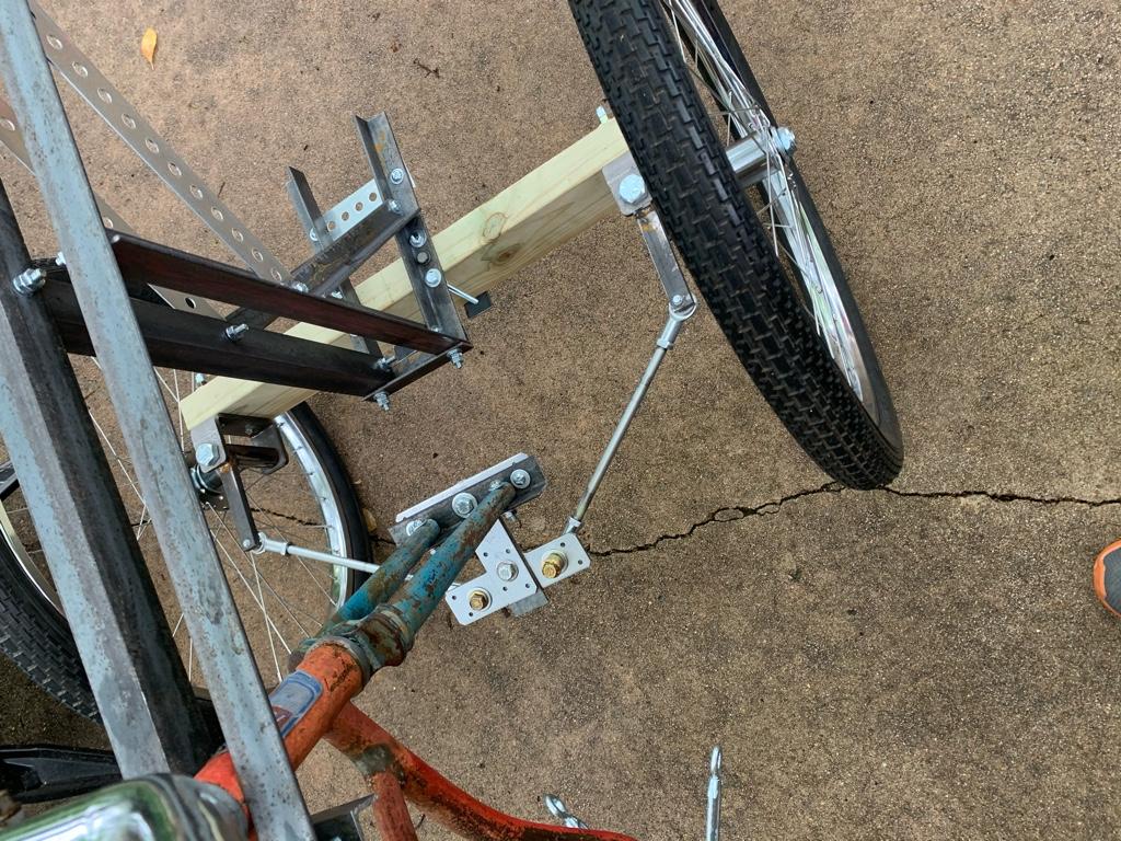
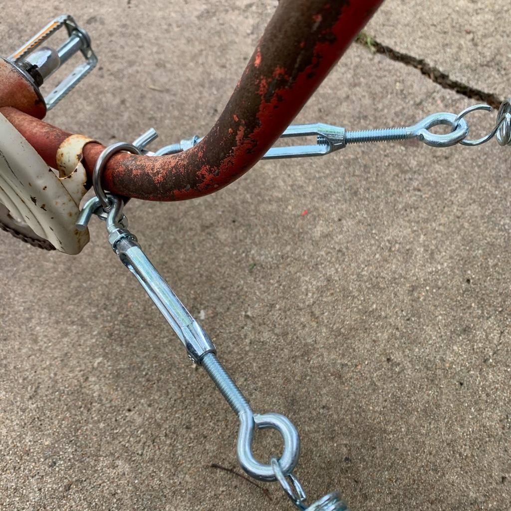
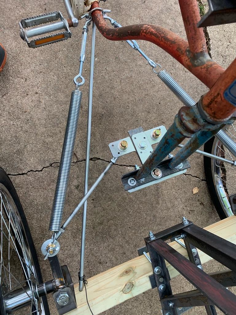
I fit the springs back for this version. They help slow and stabilize the steering. They also help keep things centered up.
Took it for a semi-successful test ride up and down street. I’ll need to recut the left tie rod to get some toe-in, out of safe adjustment, down to 1/4” bite in tie rod end.

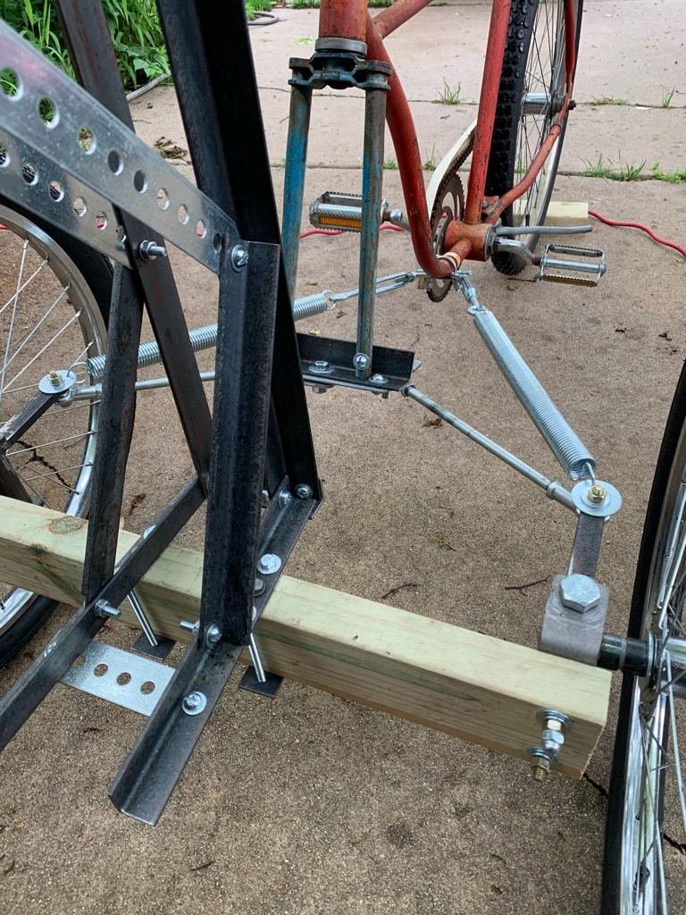
A pivot on the axle beam would be nice but that adds more potential geometry conflicts. Guess I’m getting lazy or burned out, thinking about rust colored paint for the 2x4 axle cross member.
Took it for a semi-successful test ride up and down street. I’ll need to recut the left tie rod to get some toe-in, out of safe adjustment, down to 1/4” bite in tie rod end.
A pivot on the axle beam would be nice but that adds more potential geometry conflicts. Guess I’m getting lazy or burned out, thinking about rust colored paint for the 2x4 axle cross member.
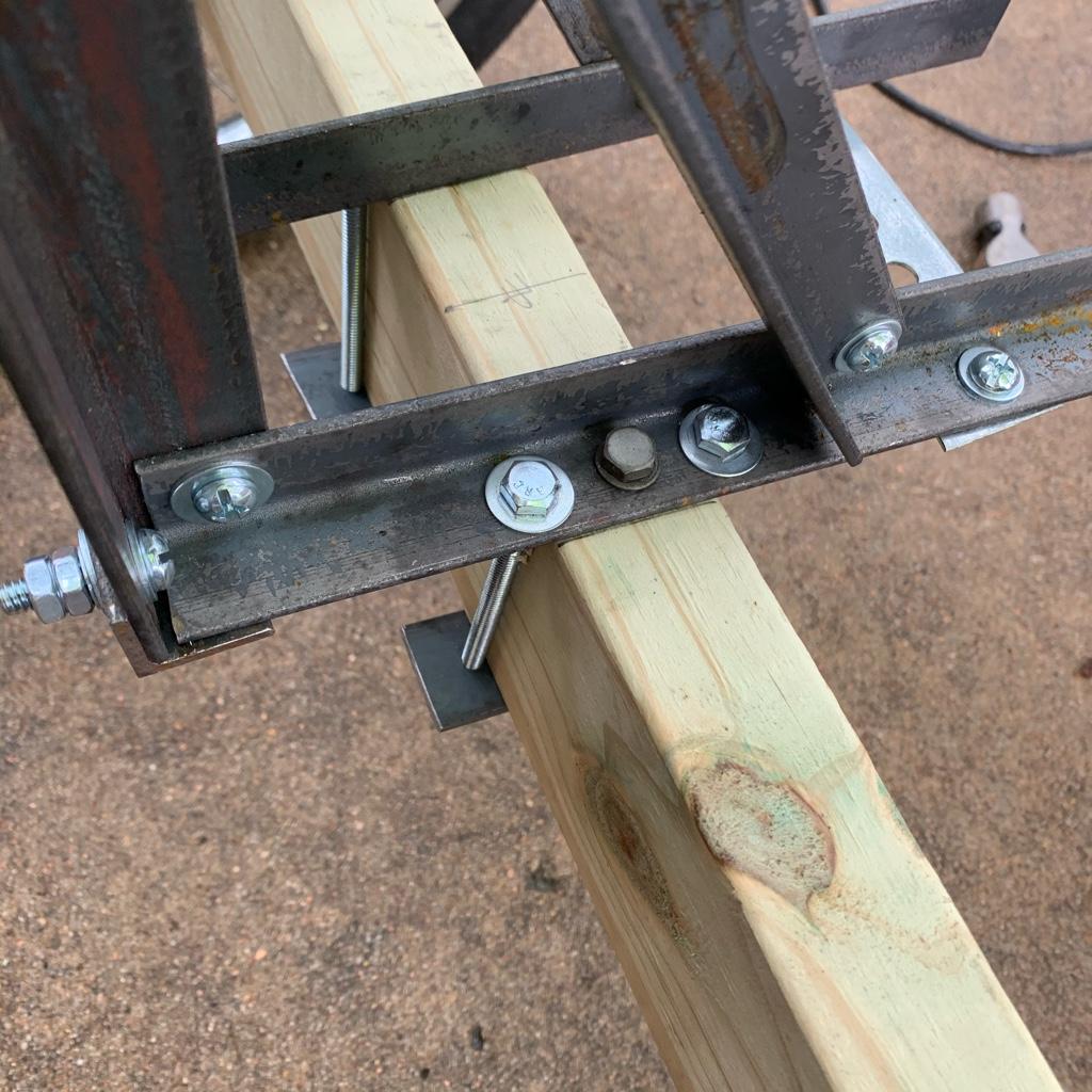
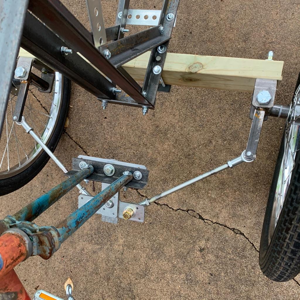
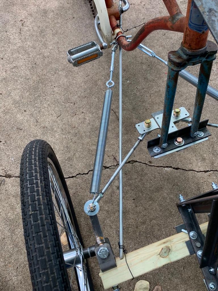
Tweaking some adjustments and adding some matching 3/8” bolt hardware. A few detail pics...
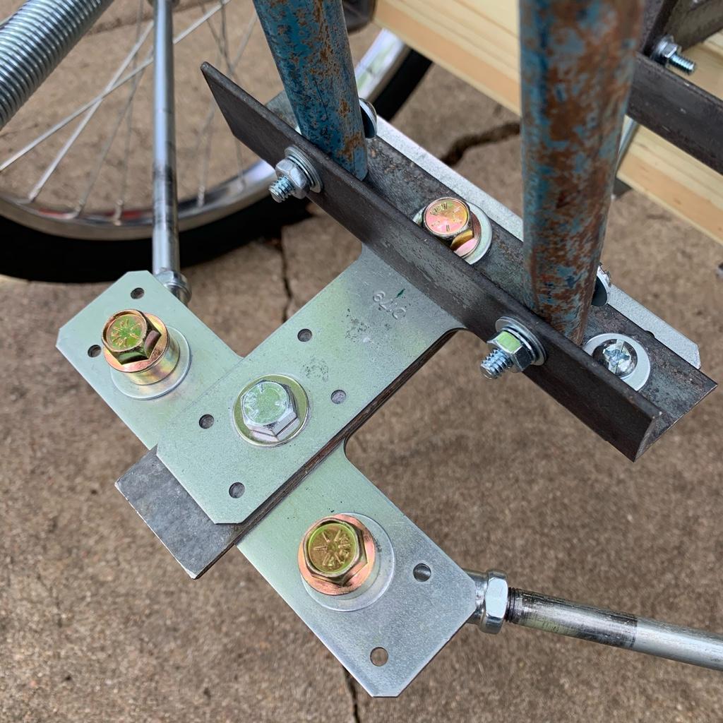
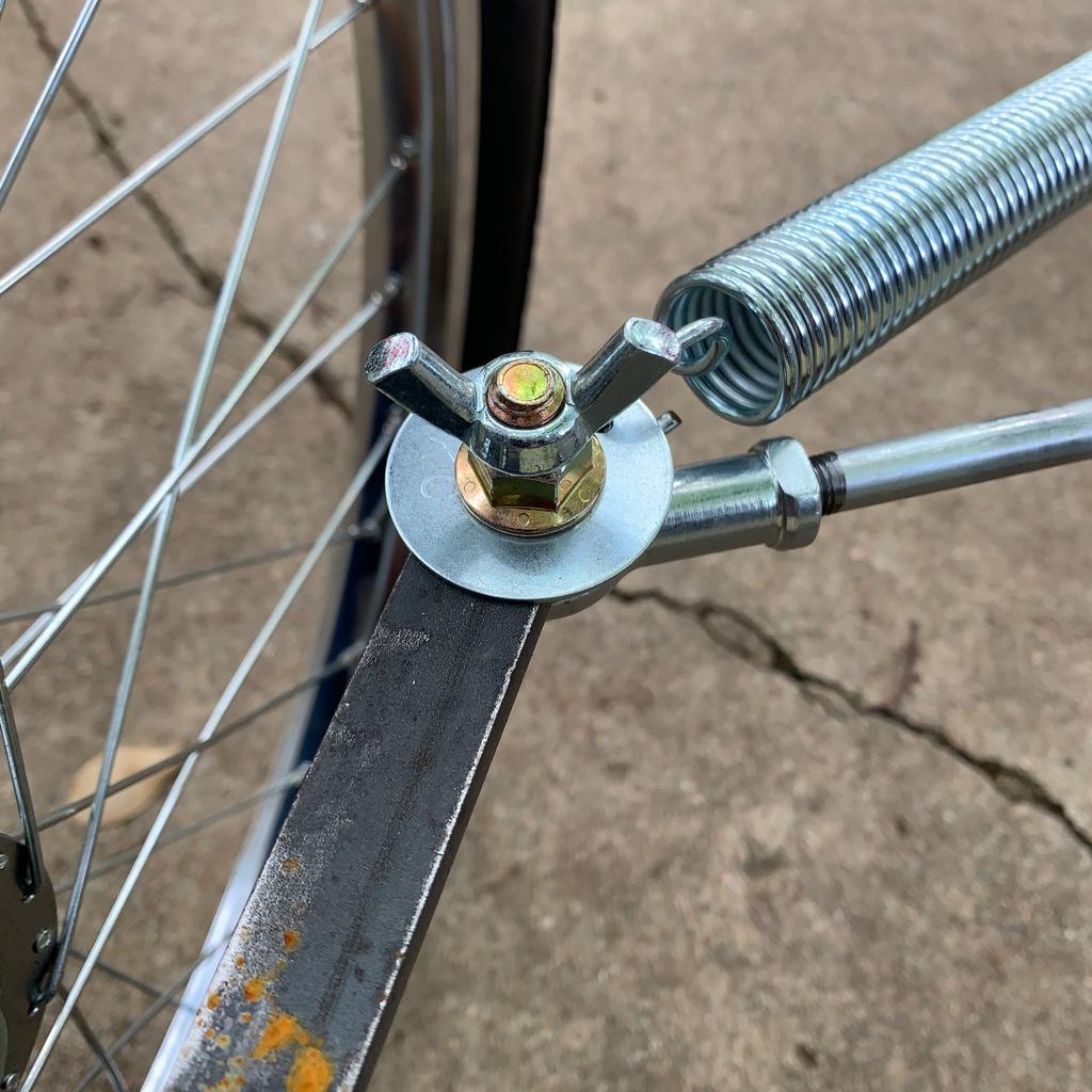
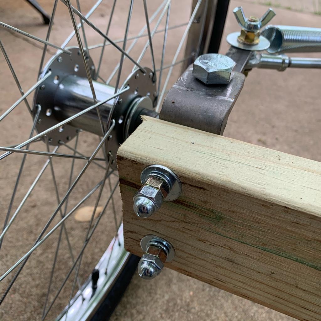

Tweaking some adjustments and adding some matching 3/8” bolt hardware. A few detail pics...
Added a 1/8” shim as the frame wasn’t sitting quite vertical.

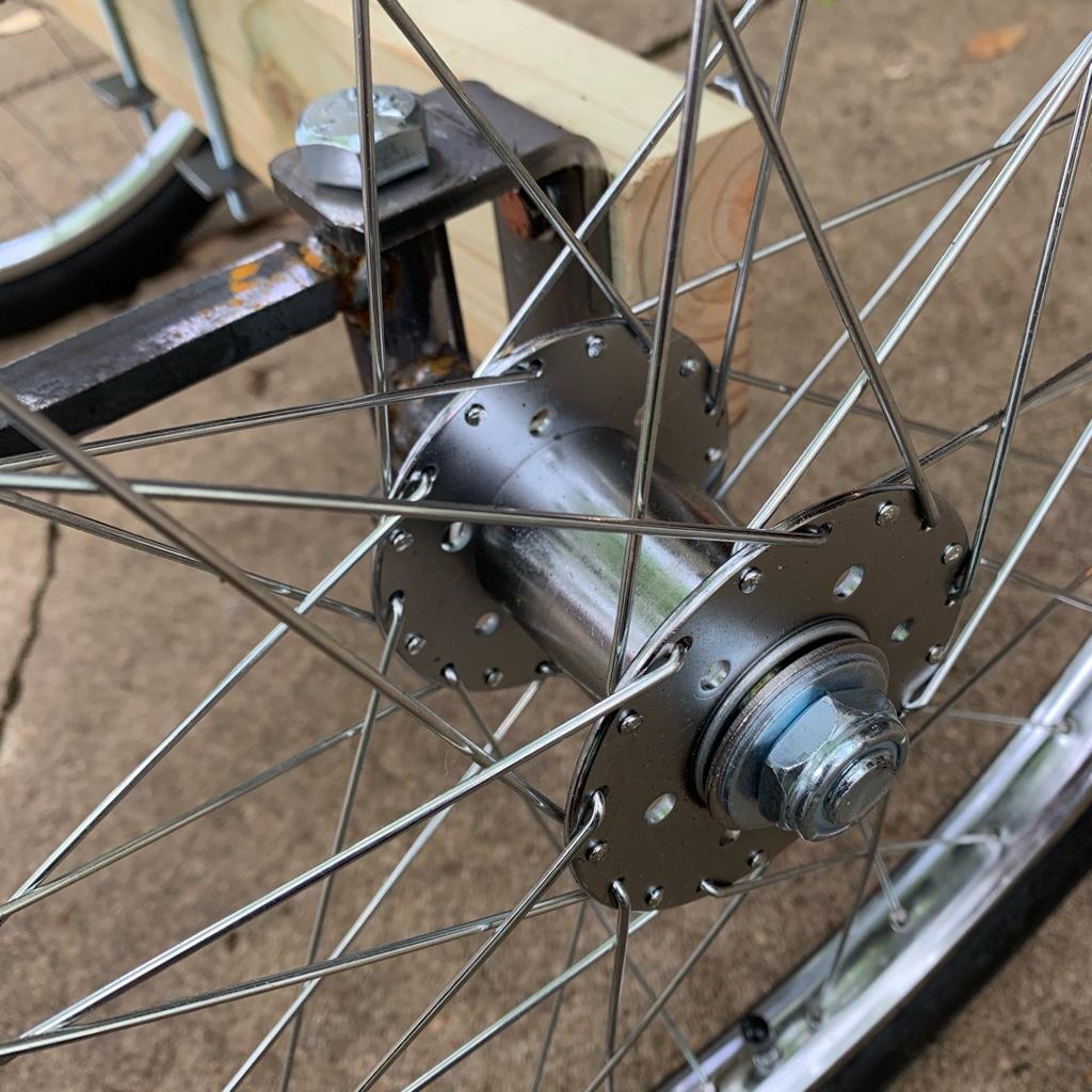
Guess I’m going to add a couple of A-frame supports from the axle beam as it has some flex when turning. Guess I’ll start with 3/8” rods as I have a couple. Or may get threaded and put a plastic cover over them. Wire should hold it, huh?
Nice to see your front coming together! Love the springs!
Perhaps a bit early to ask this, but are you going to paint those springs later in the project?
A big advantage of two wheels sitting some (corona) distance apart from each other is the fact that your chainring does not get dirty that easy
Perhaps a bit early to ask this, but are you going to paint those springs later in the project?
A big advantage of two wheels sitting some (corona) distance apart from each other is the fact that your chainring does not get dirty that easy
- Joined
- Aug 14, 2019
- Messages
- 816
- Reaction score
- 2,221
The chain will rot away in no time. When he's plowing the fields with the tractor bike, it's bound to kick some fertilizer on it!Nice to see your front coming together! Love the springs!
Perhaps a bit early to ask this, but are you going to paint those springs later in the project?
A big advantage of two wheels sitting some (corona) distance apart from each other is the fact that your chainring does not get dirty that easy
