3-Star Delusion - finally an actual ride...

Rat Rod Bikes Bicycle Forum

Help Support Rat Rod Bikes Bicycle Forum:

This site may earn a commission from merchant affiliate links, including eBay, Amazon, and others.
Re: 3-Star Delusion - aluminum bits

Definitely liking the front aluminium work on the scoops.

Also just changing the back blade to reflect the other lines and reduce the height so far.

Will wait to see the light fitted for the final look to appear then.

Great to see you keep up the momentum on this build.
 
Re: 3-Star Delusion - aluminum bits

are you going to drill holes in the plate that the scoops are attached to, so air passes through?
 
Re: 3-Star Delusion - aluminum bits

LukeTheJoker said:
Loving it Expjawa! Nice use of aluminium, now if you just had a spare $300 for moon disc covers...

Luke.

Thanks! I have a set of plastic covers, but they just don't look right IMHO. I could probably make something if I had large enough sheets to start with and the time, but I have neither at the moment...
 
Re: 3-Star Delusion - aluminum bits

Wheel discs would take away from the depth of the rims in my opinion.
 
Re: 3-Star Delusion - aluminum bits

Kroozerdave said:
Definitely liking the front aluminium work on the scoops.

Also just changing the back blade to reflect the other lines and reduce the height so far.

Will wait to see the light fitted for the final look to appear then.

Great to see you keep up the momentum on this build.

I did shorten the fin a little, but it isn't glaringly different. I might cut it much smaller - more like the fin on a '56 Caddy rather than a '59. That might even be more appropriate; I'll play with it more depending on how the tail light turns out. I have an idea as to how I can fair the light(s) in, but I'll have to pop back over to my old man's shop to snag a few things...
 
Re: 3-Star Delusion - aluminum bits

kingfish254 said:
Wheel discs would take away from the depth of the rims in my opinion.

Maybe. The rims are drilled for the spokes pretty far out from the centerline - enough so that if I wanted to relace one with a different hub I'd have to account for it in the spoke length calculation. If the spokes actually went to the center (allowing the disc to sit in that far) then I think it would look good. But since the spokes aren't really any farther inboard from the edge of the rim than on a conventional wheel, you're right - you'd mask the width of the rim and take away from the aesthetic of it. You wouldn't be able to appreciate their width.

But, either way, I don't have aluminum disc covers that fit these wheels so its a moot point, even if it is an interesting discussion.
 
Re: 3-Star Delusion - aluminum bits

Loving the scoops but i think they need another rivet it two per side to give it a more realistic aircraft look.
 
Re: 3-Star Delusion - aluminum bits

kim_dude said:
Loving the scoops but i think they need another rivet it two per side to give it a more realistic aircraft look.

Agreed. I was already planning on going there, I just ran out of rivets on hand. I'm wondering now if its worth adding rivets elsewhere to tie into that or if that would simply be cheesy...
 
Re: 3-Star Delusion - aluminum bits

I think a few well placed rivets would be kool beans.
 
Re: 3-Star Delusion - rivets and screws

Time for a progress report. I've spent most of the last couple days working on the bodyworl for this bike. I even took Wednesday, Thursday, and today off from work (I have vacation time to burn with no trip planned this summer) to do it. So here we go. Everything started off with a trip to Home Depot for hardware and paint. Hopefully I'll get to the later today. But before I could do that, I had to actually fasten everything together and figure out how some of these parts were really going to mount on the bike.

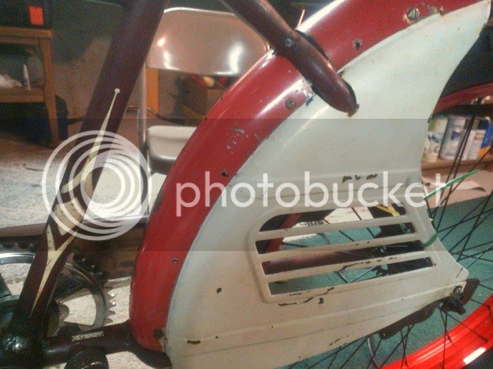
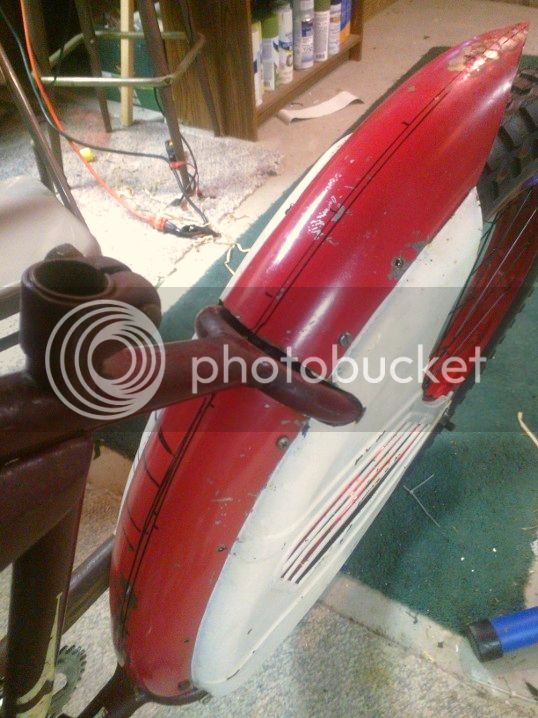
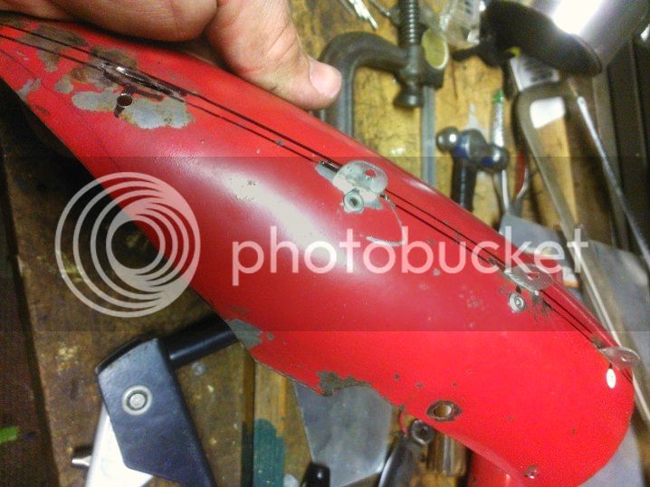
For starters, I drilled out additional holes to attach the fender sections to the skirts. I know that Higgins did a decent job in that department, but I wanted to tie into the riveted look previous discussed regarding the front panels. So here's that:
WP_001507_zps20d835ff.jpg


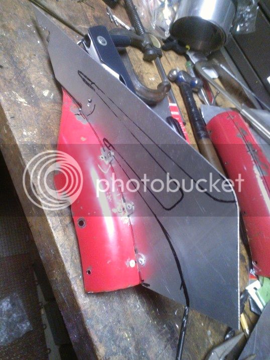
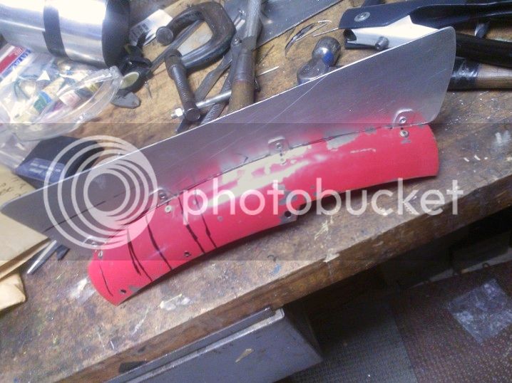
Then with the fin sections in place, I marked out the center line of the fender - or, more specifically, the where the sides of the fin will be.
WP_001508_zps83fb34b5.jpg

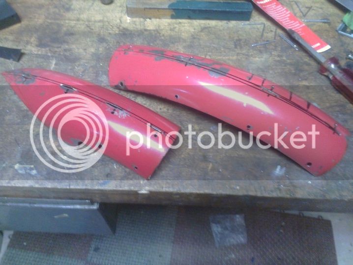
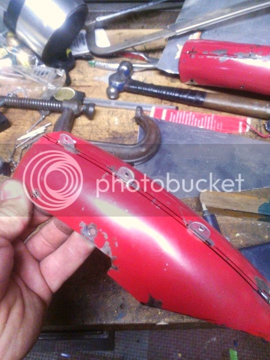
I used that as a basis for determining where the mounting tabs for the fin will go. I elected to make up small angle brackets that slot through the fender from underneath that the fin itself will be riveted to. Unfortunately, I forgot to add tabs to the fin when I cut it out of the sheet, so the added brackets became necessary. The fenders were then slotted with an abrasive grinding wheel in the Dremel (again, one of the handiest tools ever).
WP_001510_zpsf7ef21ac.jpg

The slots were offset, as you can see, so that they'd attach to the side of the fin while it was centered.

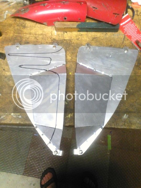
At this point, I diverted to the front scoop panels. These were drilled for additional rivet holes and for mounting brackets. For that function, I've use small, alloy P-clamps / cable hangers for 1/4" wiring. The truss rods are actually closer to 5/16" in diameter, but this allowed with to form them to fit over the rods and potentially achieve a solid retention method. The mount rackets are attached with machine screws rather than rivets becasue I had no rivets large enough in diameter. That's probably for the better. Here are finished parts:
WP_001509_zpsbf3c844f.jpg


And now, I'll post this and continue this train of thought in another post...
 
Re: 3-Star Delusion - rivets and screws

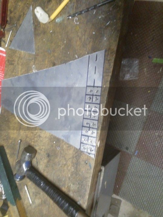
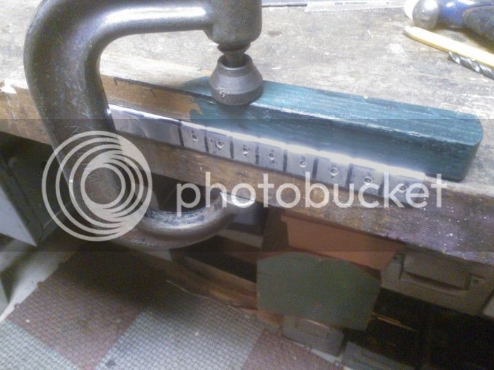
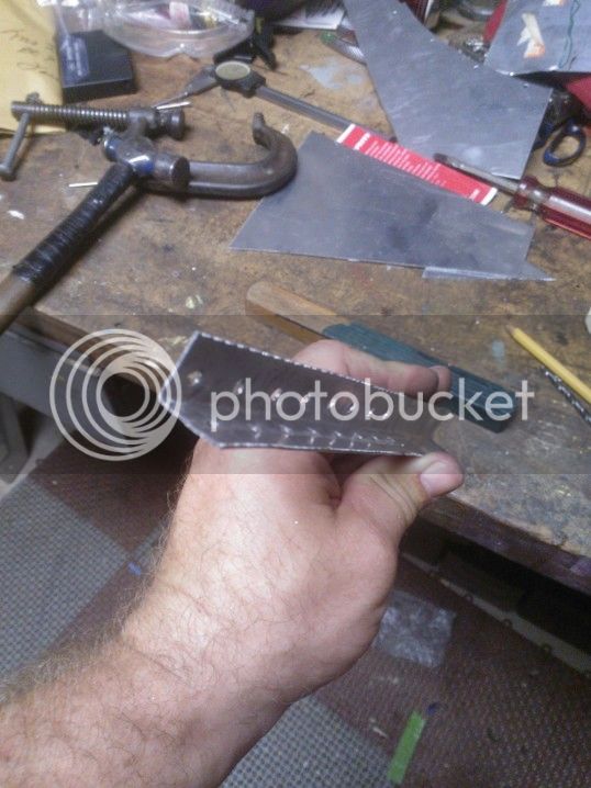
OK, this dilusion continues. I used a scrap of the aluminum sheet that the fin was cut from to make the angle brackets. These were measured and marked out. The holes were drilled, the angle was formed, and then they were cut on the bandsaw.
WP_001512_zps48b7415b.jpg

WP_001514_zps8e98a7d2.jpg

WP_001515_zpsfb22d0a0.jpg


The next step was grinding corner radii on them while deburring on the sandbelter. They were then popped through the slots in the fender and riveted in.
WP_001516_zps7306052a.jpg

WP_001518_zpsc4974e49.jpg

Fender or stegosaurus? You decide...

From here, the fin hole pattern was drilled and few other trimmings done:
WP_001511_zpsec071830.jpg

Yes, there's a cork on the end of the fin because the point is sharp. It was riveted onto the tabs on the fender:
WP_001519_zps9ba935ef.jpg

This was repeated for the lower fender:
WP_001522_zps1090e466.jpg
 
Re: 3-Star Delusion - rivets and screws

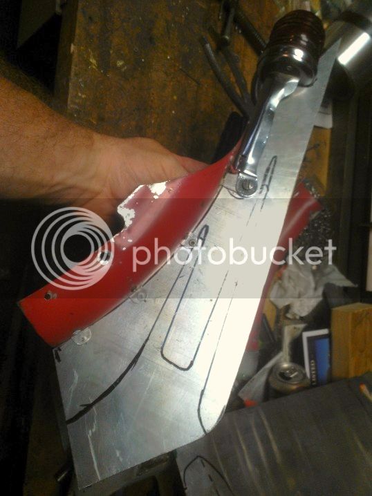
You may have noticed at this point that there was a relief cut in the bottom of the rear of the fender and thought "what could that possibly be for?" Well, I'm here to clear up the mystery. There was all that talk earlier regarding what to do about a tail light. I though about attaching a Delta rocket light to each side. I considered hacking up that Jaguar headlight and appending them to the sides of the fin. I even considered Kingfish's suggestion of an LED strip up the rear of the fin. All worthy ideas, but not really what I'd envisioned.

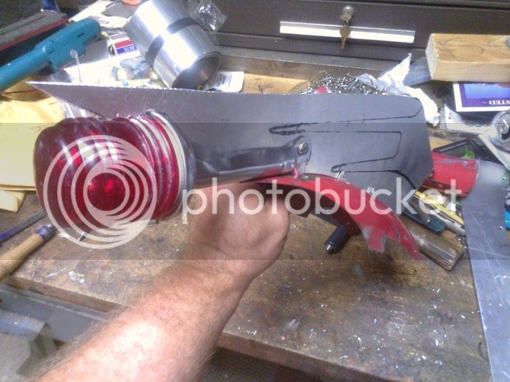
One step closer to what is in my head is making use of the red marker light from Big Beam lantern that was disemboweled last year. The lamp base is part of the extension arm that attaches it to the lantern's handle. So I have to use it complete if I want it to work. The relief, or slot, under the fin gives that someplace to slide into the assembly. Here's what I mean:
WP_001520_zpsb3c52095.jpg


Its retained using the pivot bolt hole on the end of the arm. It also fits snugly between the fin and fender, so it can't really move about. I've notched the end of the fin to allow the globe to be set into it somewhat.
WP_001521_zps97f49c50.jpg


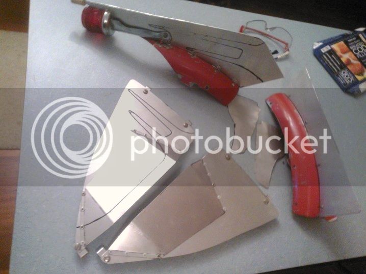
I also closed up the cross section of the arm to try to get it to fit close to the side of the fin, but as you can see, there's still a gap. It might not be quite as integrated as I'd like, but it's close. Here's the product of a couple day's labor, all spread out on the kitchen counter:
WP_001523_zpsc4b9accc.jpg
 
Re: 3-Star Delusion - rivets and screws

Thanks. One last bit before I get back to work.

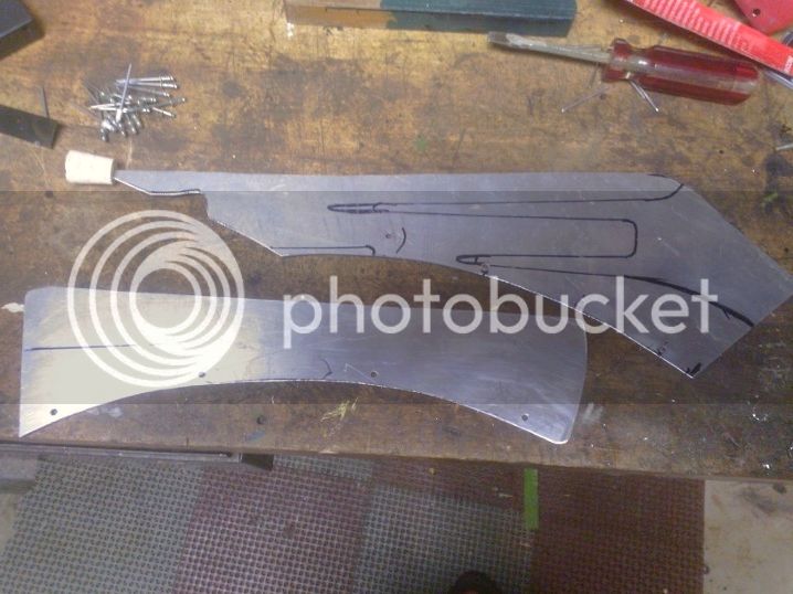
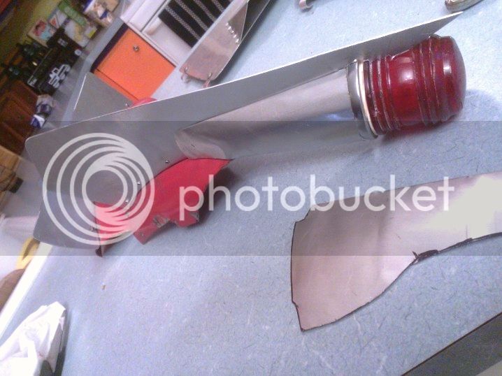
The tail light came out pretty well, I think, but I'm still tracing the idea of better integration into the whole. There are pair of flat pieces cut from aluminum flashing in the above picture that I haven't mentioned yet. These are for an idea I had to better streamline the tail light into the fin, more like the Cadillac design.

I worked out the shape with a few phases of template before I got to what you see here. But with a bit of (careful) hand forming, they make a nice cover over the lamp handle arm.
WP_001527_zpsf709ee72.jpg


This does, admittedly, hide the visual impact of the pointed fender flowing into the pointed fin. The overall improvement in appearance, though, makes it worthwhile IMHO. I think that you can still see that the fender flows into the shape of the fin, it just does through a streamlined fairing for the light. I like the way this came out, its much more like what I intended when I started. The streamlined tail light is sort of the polar opposite of the very non-streamlined headlight, as KF noted before. So there's a bit of dicotomy there, but I think that makes it all the more rat-like (if I may be permited to consider that sort of thing). I still have to figure out an effective way to keep those flashing fairings in the fin. They're held on with double-side tape in the picture, but it doesn't hold it real well and is by no means permanent. I'll have to think about that one.

I've since test fitted all the parts back on the bike and taken some added photos. They're still on my phone, however, so I won't post them till later. By them I hope to have everything painted...
 

Latest posts

Back
Top