Got to put the hub together tonight, figured I take a few pics how it works ...
Parts diagrams can be found at trfindley.com
here if anyone needs a link.
If you wondered how they work here are some pics of the drive parts.
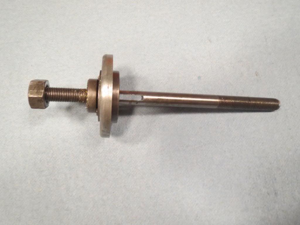
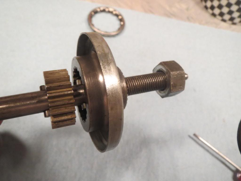
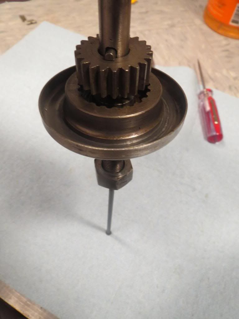
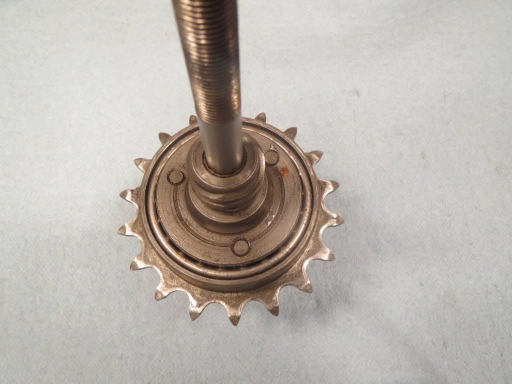
The axle assembly comes like this (the dust cap and axle nut can be fully removed)
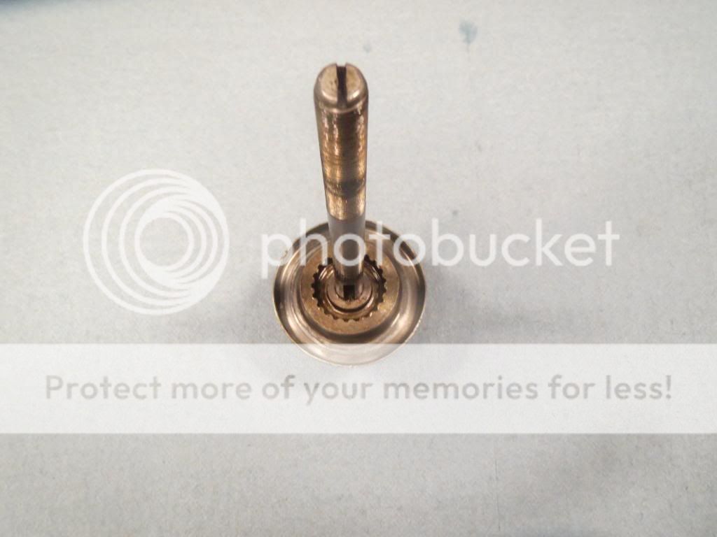
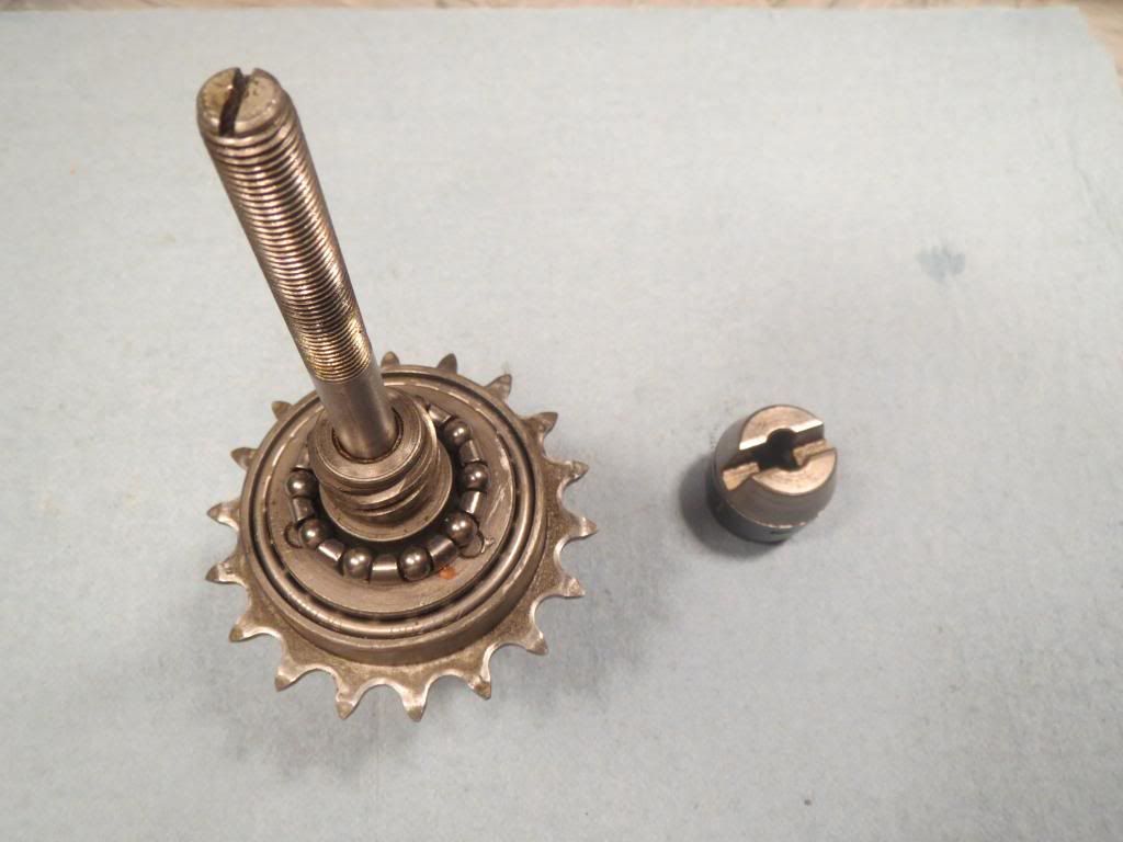
In this second picture you can see where the sun gear gets "locked" to the axle.
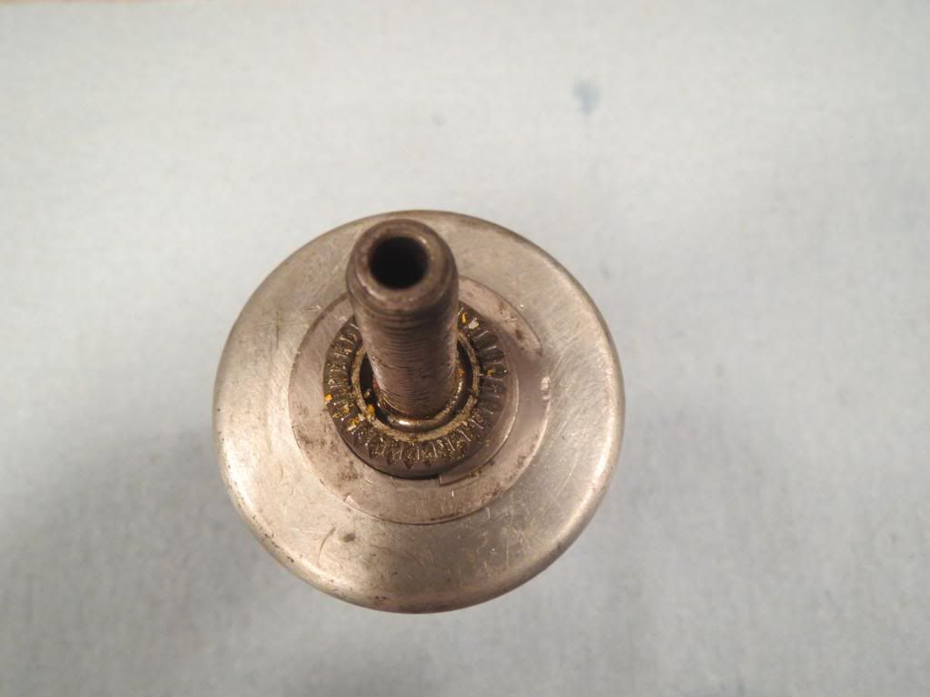
In this third picture you can see the drive side of the axle is hollow, this is where the shifter rod goes in at.
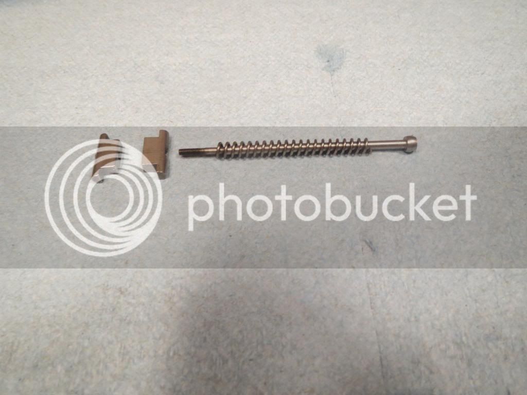
In this fourth picture you can see the shifter rod w/spring and the "yoke" pieces that hold the sun gear
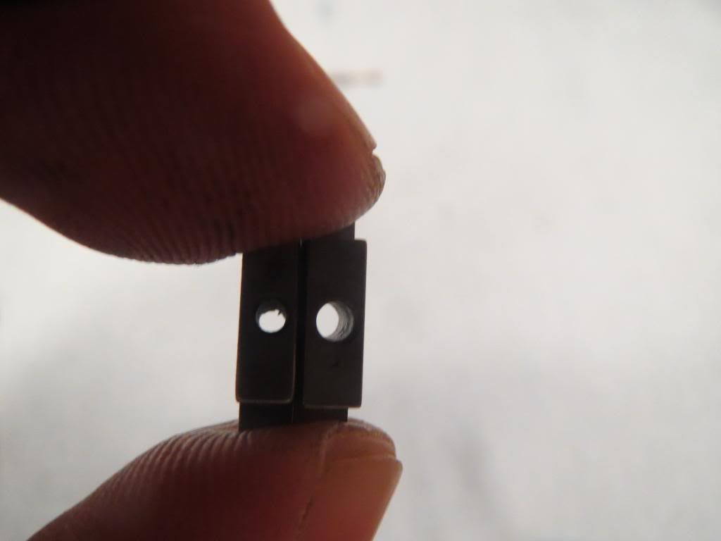
In this pic you can see that the yoke piece on the right has a larger hole, the rod goes through this one first and then threads into the other threaded yoke piece. Whe assembled the sun gear will be between the 2 yoke pieces.
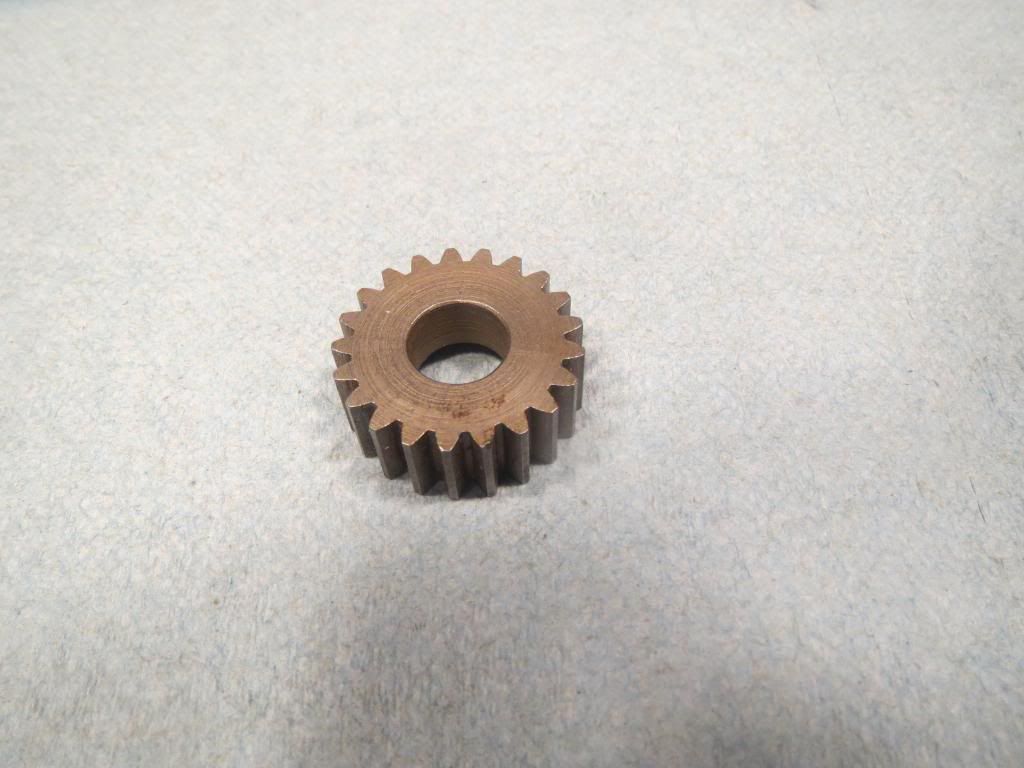
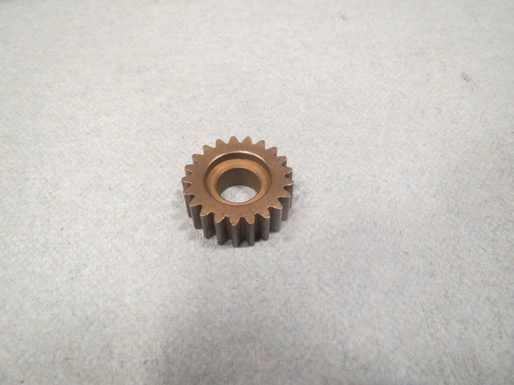
In the sixth and seventh pic is the sun gear, the smooth side is to be mounted facing the brake side, the recessed side faces the drive side.
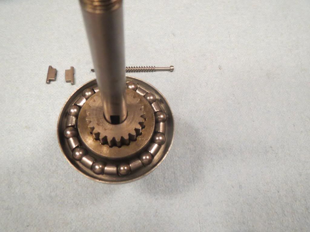
This eigth picture shows how the sun gear should sit in the assembly, the shifter rod and yokes should be installed before you go any further. This picture also shows a bearing in place, the bearing can be put in place after the shifter rod has been installed.
In the ninth picture you can see how the yoke pieces slide into the axle slot around the sun gear, the your ready to tighten up the shifter rod through the axle. Its a little tricky because you are pushing the shifter against spring pressure but once it starts threading into the yoke, start tightening slowly, otherwise you may break the threads off the shifter rod.
In the tenth pic, the shifter rod is tight and I am pushing on the shifter pin (I'm using a spare piece of shifter rod to reach in the hub), this pic shows how the sun gear is "unlocked" from the axle.
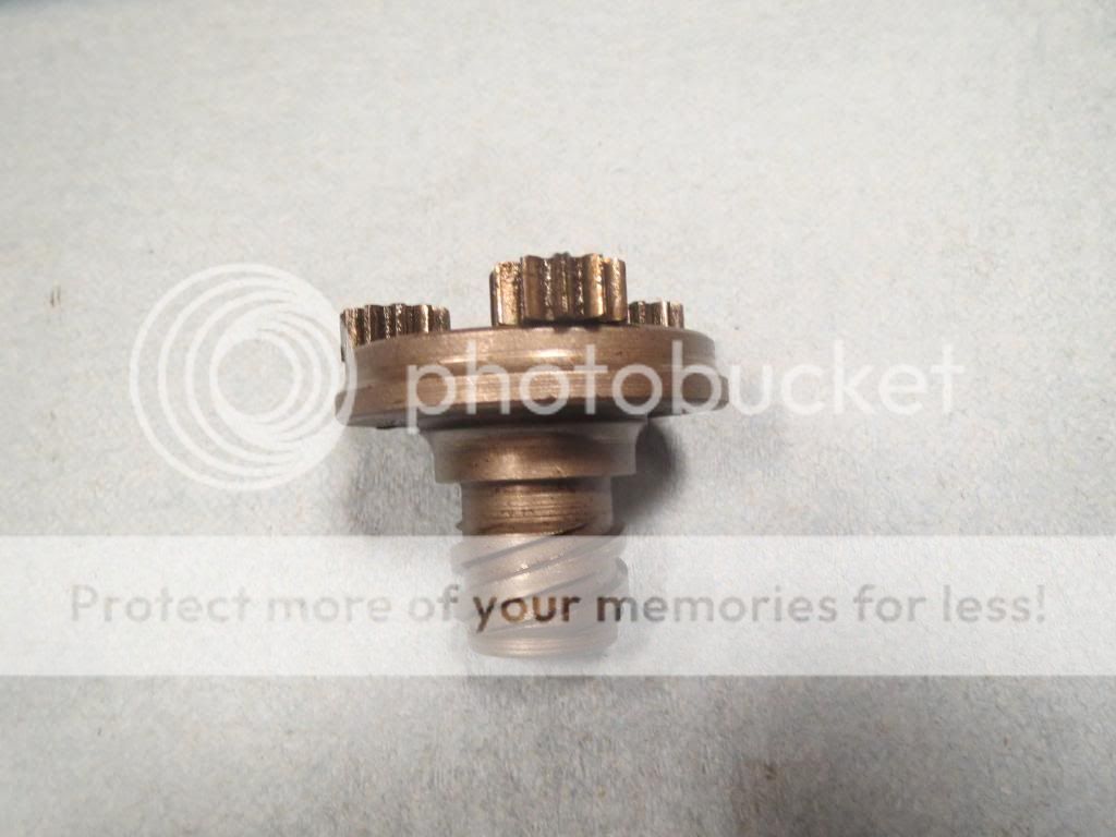
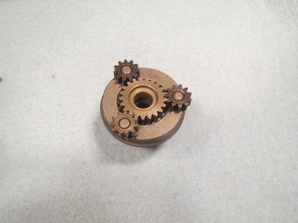
Here is the hub driver with planetary gears
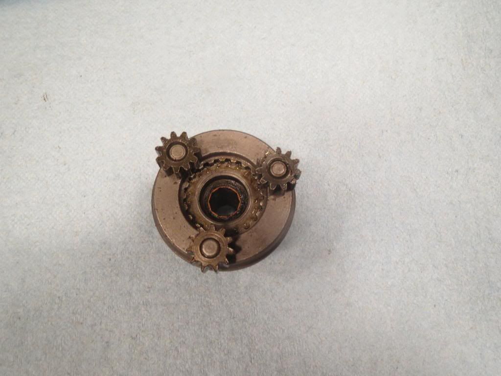
This picture shows the hub driver with the 3 smaller planetary gears, when shiting the hub, you want the sun gear to be "locked" into this piece.
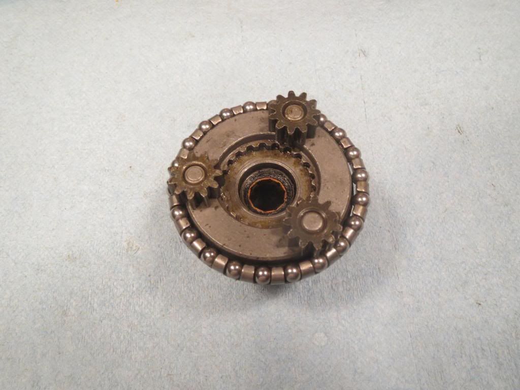
And this picture shows the Sun gear in place on the driver. As the sun gear moves from being "locked" on the axle to being "locked" on the driver, the 3 smaller planetary gears on the driver will always touch the sun gear. So if the sun gear is locked into position on the driver, this keeps the planetary gears from spinning as well, which keeps the ring gear / sprocket turning at the same rate as the hub. 1 turn of the sprocket will equal 1 turn on the hub.
There is also a large bearing cage that must go onto the driver before the planetary gears are in place
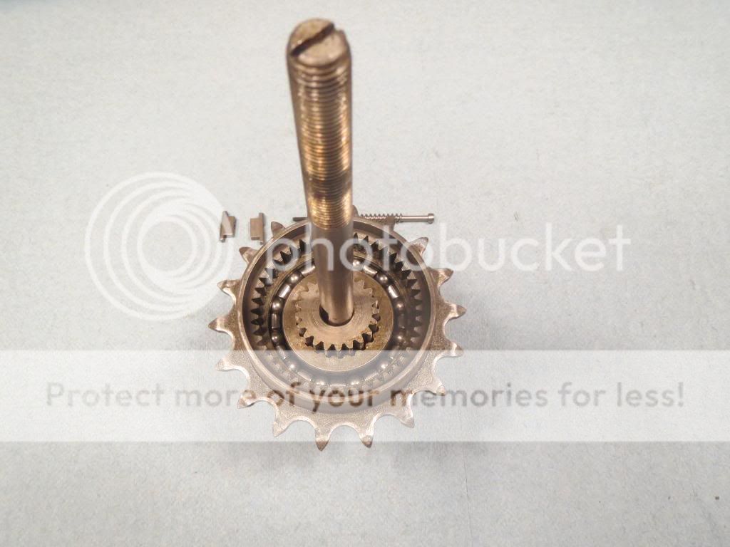
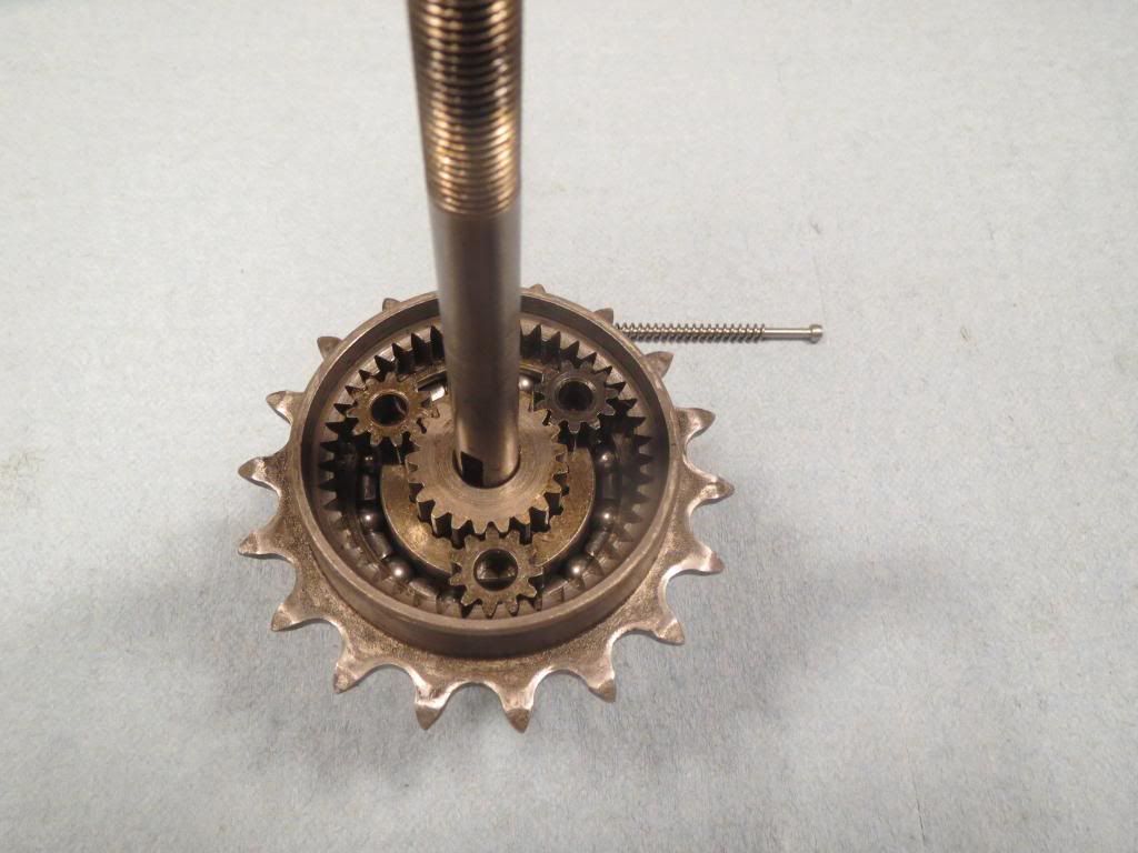
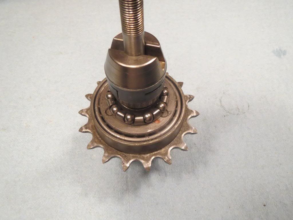
Here is the sprocket / ring gear assembly
In this picture you see how the sun gear / planetary gears and ring gear are connected when in place. This picture shows how the internals would be with the sun gear "locked" to the axle. When the sun gear is locked to the axle and the ring gear / sprocket assembly is pedaled normally, this causes the "gearing" to change. The driver and clutch assembly will move with the planetary gears because the planetary gears are attached to the driver by the pins the planetary gears rest on. The driver is still the only part that rotates the hub. In this position your hub will turn slower than the sprocket giving you lower gearing making hills easier to pedal. When there is no pressure on the shifter rod, this is the gearing you are in.
Here you can see the driver in place. At this point the sun gear / shifter rod / outer drive side bearing cage / ring gear & sprocket assembly / driver with large caged bearing and planetary gears should be installed.
The larger of the two remaining bearing cages goes on the driver like shown, everything you see assembled in the pics should be greased while assembling before it goes in the hub. Once you reach this point you put the axle assembly into the hub through the drive side. Once it is in the hub, the clutch driver seen to the right should be slid onto the axle from the brake side.
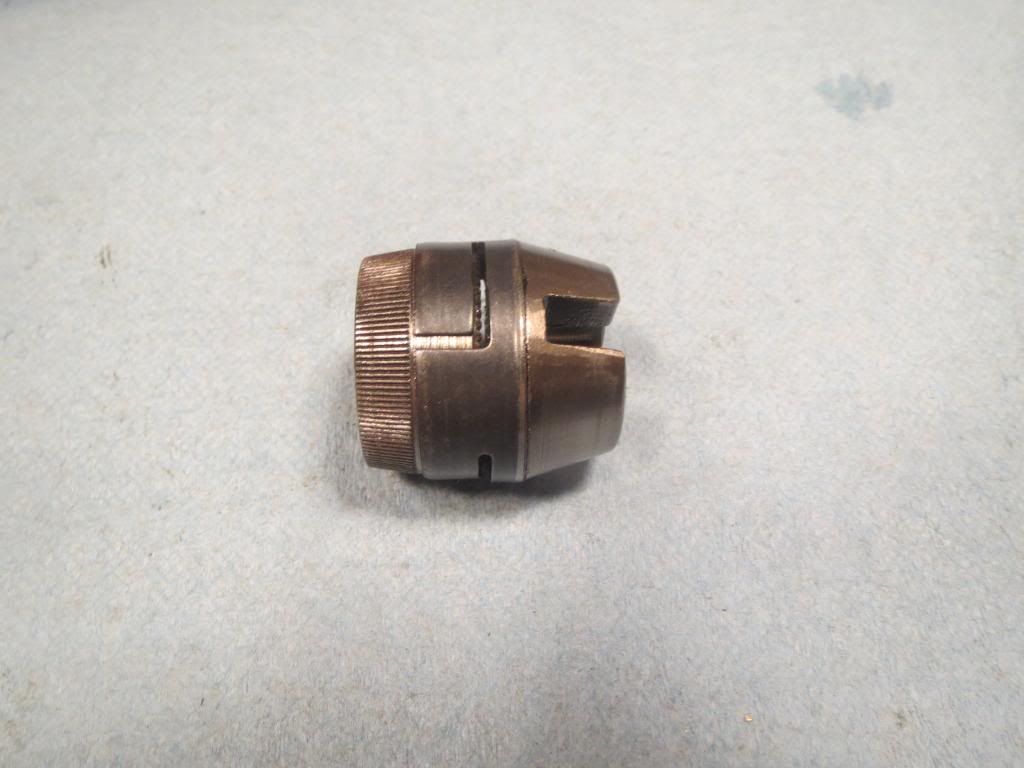
Here is the clutch driver, which is also attached to the brake expander. This is how it looks assembled together.
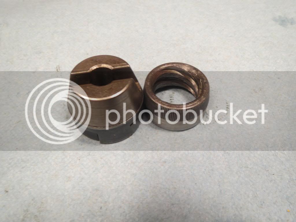
This is the same part pulled apart, the clutch driver is on the right, you can see it is threaded to match the clutch driver. When you pedal forward the sprocket moves the driver so that the clutch is pulled tightly towards the internal hub lip making contact with hub shell, you can see a line worn in the ribbed part of the clutch, this is what grabs the hub shell and causes it to actually turn the wheel.
This is how it threads onto the driver though the hub should be installed over the drive parts before the clutch is is slid onto the axle.
Once the hub is in place and the clutch and brake expander is on, pedaling forward threads the clutch onto the driver making it grab the hub as stated above, back pedaling unthreads the clutch, the clutch gets pressed against the brake expander and the brake expander is pushed towards the brake side of the hub. When this happens it pushes the brake shoes against the internal walls of the hub making it stop. There is nothing different from the way this brake operates from a single speed Bendix RB coaster hub.

