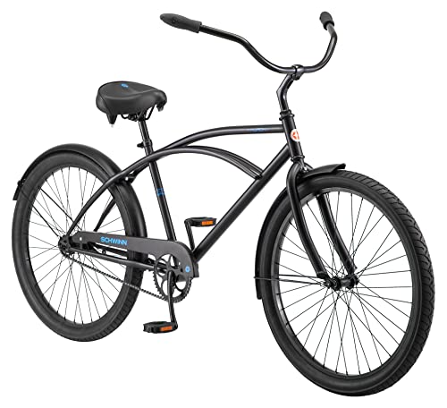
It doesn't appear to me that wires in the positions you show them, would have much effect on stiffening the structure. In a stick and wire structure, like the box kites that were early airplanes, wires are tension elements, and wood struts are compression elements. They should be placed in opposition to create a rigid structure.
If the lower wire you have running close to the frame tubes was instead held some distance below the crank, on a compression strut, that could take some of the wheel forces in tension. Like the support cable on this crane is supported on a strut high above the body.
View attachment 222912
I don't envision the central cables from head to rear wheel dropout plate being loaded in tension with the rider on the bike, and if they were, they could bend the head tube if placed as you show. My gut says that they will just hang there limp, but I'm no expert in bike design.
If you draw a simple sketch with the imposed loads, (upward at the head and rear wheel, in opposition to the downward rider weight at the seat post) you might better visualize what each element is being asked to do. I'd model the crank load as being the rider weight placed on the crank rather than the seat, as a starting point. Of course, in actuality, all static loads will be much higher dynamic loads, but you have to start somewhere.
After a simple load sketch, the next step in structural analysis might be free body diagrams of each of the four major corners. These are simplified sketches with constraints and imposed loads, like these examples:
View attachment 222913
Yours will be indeterminate structures, because they are over-constrained, and it's difficult to know how much of the load is taken by each of the elements, which are taking forces in bending as well as in tension, compression or shear. Indeterminate structures are analyzed by considering the relative values of the modulus of elasticity of the various elements. With some small deformation theorytically imposed, the resulting reaction forces of each component of the structure can be calculated to see how they contribute to carrying the total load.
In my opinion, the classic bicycle frame shape is at least somewhat married to the strong points of steel tubing. In other words, the design evolved because steel tubing was available.
Look at how different this bicycle designed from scratch to be built from plywood is from the standard metal frame:
View attachment 222914
Rather than use any "stick" elements, plywood is strongest at resisting the largely in-plane loads, when formed as a largely vertical sheet. Holes can be cut from the lower stressed sections. Lateral stiffness is obtained by using two sheet frame elements, arranged in a box some distance apart.
The following design is more along the lines of something familiar, but notice how the main frame is configured as a TEE section, and various elements are arranged with their largest dimensions either parallel to the main plane, or transverse to it, depending on how the designer wanted the stiffness and load capacity. They didn't try to make a wood fork though, that was too much of a challenge.
View attachment 222915
Your "box kite" idea can work, but I suggest thinking further outside the traditional safety bike frame design.


